
High-gain circularly polarised planar antennas for cubesat systems
Design and analysis of superstrateintegrated differentially-fed circularly-polarised antennas are presented. The antenna consists of a metallic patch fabricated multilayer space-qualified printed circuit boards, integrated by a dielectric superstrate on top to establish suitable resonant condition for high-gain operation. The driven patch is excited by two orthogonal differential feeding pairs using sequential rotation technique for pattern symmetry and generation of circular polarisation.
The proposed antenna exhibits an impedance bandwidth of more than 10% with peak gain of more than 17dBiC across the frequency band of interests, which lends itself being suitable for CubeSat missions at X-band.
Planar antennas are widely used in high-performance aircraft, missile, spacecraft and satellite systems, where size, weight, cost, performance, ease of installation and aerodynamic profile are constraints [8]. For CubeSat platforms, antenna designs that do not require deployment are relatively preferable with low profile and direct interconnection to the rest of the system. They have been extensively adopted and built on 1U footprint of 100x100mm to generate broad half-power beamwidth (HPBW) with acceptable gain and circular polarisation (CP) performance for coverage of the systems operating at typically from UHF to S-bands.
Recent enquiries have been raised for deployment-free antenna solutions that provide high gain with good CP performance at X-band and higher frequencies for deep space missions and inter-satellite links, whilst being accommodable to minimum footprint on the spacecraft. Such has encouraged to look into various solutions using planar antenna designs to achieve the requirement.
Horn antennas and microstrip patch antenna arrays are typically considered for systems where intermediate to high gain (≥20dBiC) is required. Horn antennas are inherently linearly polarised, and polarisers are needed to generate CP waves. Relatively small footprint is required on the platform for assembly, nevertheless, they have to be physically long enough to focus the beam, which lend themselves being unsuitable for small satellites. On the other hand, more flexibility can be acknowledged from microstrip patch antenna arrays, on which radiating
elements can be configured to generate CP waves and produce the required gain.
More patches in an array forming larger aperture size can produce beams of higher directivity, however, its associated feeding network becomes more complicated, resulting in more ohmic losses, particularly at mm-wave frequencies. This leads to investigation on the feasibility of low-profile designs with more flexibility, which are able to achieve all the requirement, whilst still being applicable to 1U footprint.
A number of research work [1-2] have been proposed on the use of single driven element incorporated with engineered superstrates on top to produce narrow beams with high gain. In this work, a high-gain circularly polarised planar antenna operating at X-band using loaded dielectric superstrate with predetermined dimensions on top of a circularly polarised differentiallyfed driven patch is proposed.
The driven patch is fabricated on space-qualified printed circuit boards (PCBs), energised by two orthogonal differential feeding pairs of planar transmission lines separated by a shared ground plane in the middle to produce CP waves with low axial ratio and symmetrical radiation patterns across the operating frequency band. The relative dielectric constant and thickness of the loaded superstrate are selected so that the resonant condition can be generated, which co-interacts with the driven patch to focus the beam. Detailed analysis and implementation are given followed by simulated results to validate the deigns.
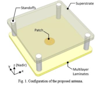
Configuration of the proposed antenna is shown in Fig. 1. The antenna consists of a circular patch fabricated on a dielectric layer of predetermined thickness to provide acceptable CP performance with adequate impedance bandwidth. The patch is fed by two pairs of microstrip tracks at the bottom, separated from the patch by a common ground plane sandwiched in the middle to minimise interference with more design flexibility in comparison with conventional designs.
As shown in Fig. 2, a dielectric superstrate is loaded on top of the driven patch suspended by four standoffs of predetermined length (TVAC). The distance from the ground plane to the inner face of the superstrate, defined as Teff, is selected so that high-gain condition can be realised.
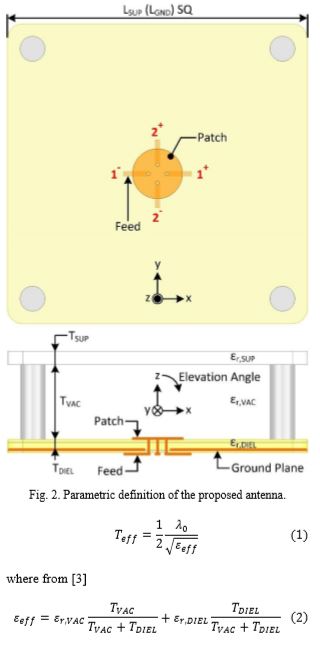

The driven patch is fed by four pins realised by platedthrough-holes that are electrically connected down to the respective tracks at the bottom of the PCB. The amplitude and phase of the signal from the tracks to the patch are defined so that CP waves can be produced [5-7], whilst generating symmetrical radiation patterns at nadir. This is realised by feeding the patch with two orthogonal pairs of differential signals, whose excitation coefficients are 1e-j0, 1e-jπ, 1e-jπ/2, 1e-j3π/2 at port 1+, 1-, 2+, 2-, respectively, producing right-handed circularly polarised (RHCP) waves, whilst as of 1e-j0, 1e-jπ, 1e-j3π/2, 1e-jπ/2 at respective ports to generate left-handed circularly polarised (LHCP) waves. To investigate the impedance match of the antenna using differential feeding technique, the voltage standing wave ratio (VSWR) of the patch as defined by the two differential pairs can be expressed as show below.
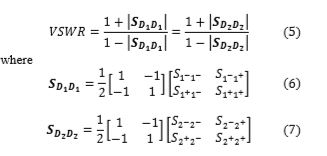
These are reflection coefficients of the patch when driven by the two differential signal pairs defined by the single-mode S-parameters of the ports. Typically, VSWR of 2.0:1 measured from the port of the antenna is adequately low for low-power systems with peak power of up to 5W, whilst that of 1.5:1 is required for higher input power. The proposed antenna is designed to operate at 8.08.5GHz, centred at 8.25GHz. To validate the theory, the size of the patch is calculated [8] based on selected values of relative permittivity (εr,DIEL) and thickness (TDIEL) of the substrate underneath, so that it operates at the centre frequency of the band of interests.
The thickness of the superstrate (TSUP) is obtained using (3) based on the required resonant condition; εr,DIEL ≥ 10.0 is considered in this work, which is found to be adequately high to implement high-gain condition. A preliminary value of distance from the surface of the patch to the inner face of the superstrate (TVAC) is selected and optimised with the location of the feeding pins to obtain minimum VSWR at the ports as defined. Parametric analysis is then performed to investigate the performance of the antenna with respect to its footprint in terms of operable bandwidth (VSWR), peak gain, half-power beamwidth (HPBW), and 3dB-axial-ratio beamwidth (ARBW).
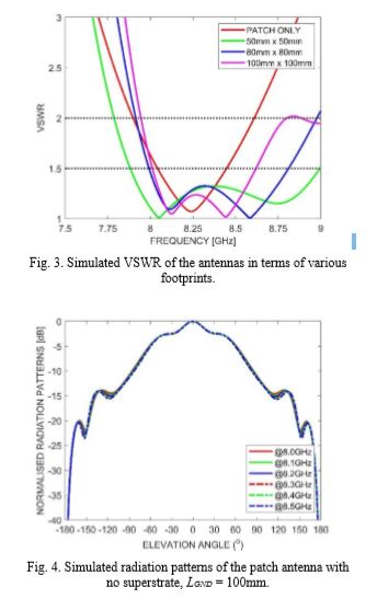
The proposed antenna is analysed and optimised using ANSYS Electronics Desktop 19.1, a full 3-D electromagnetic simulation package, and comprehensive parametric analysis in terms of the dimensions of the antenna is performed to investigate the relationship between field parameters and geometrical variation of the antenna. It is seen from Fig. 3 that integration of the superstrate broadens the impedance bandwidth of the antenna in comparison with the patch without the superstrate, which is effectively the combination of two types of resonances; one is from the resonance of the patch, and the other is that established by longitudinal electric fields oscillated between the superstrate and the ground plane of the antenna.
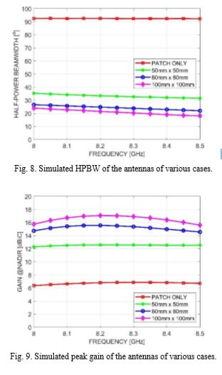
Radiation patterns of the proposed antenna are shown in Fig. 4-7, which are generated by the excitation of the patch in RHCP mode as defined in section II, to demonstrate that use of the superstrate effectively focuses the fields radiated from the patch to generate sidelobe-free beams with consistency of HPBW, as shown in Fig. 8, across the frequencies of interests.
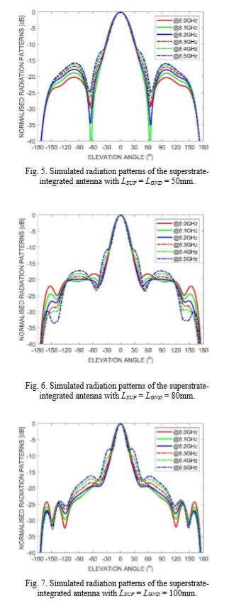
Results of peak gain at nadir in terms of various sizes of the superstrate; 50x50mm (1.39λ0 x 1.39λ0), 80x80mm (2.22λ0 x 2.22λ0), and 100x100mm (2.78λ0 x 2.78λ0), are shown in Fig. 9, where λ0 is free space wavelength at 8.25GHz. It is found that peak gain at nadir becomes stable at 17.0-17.5dBiC when the size of superstrate is more than 3λ0 x 3λ0. Fig. 10 shows the simulated results of 3dB axial ratio beamwidth of the proposed antenna. It is realised that there exists an optimum range of size of the superstrate to produce acceptable performance for the application.
Design and analysis of superstrate-integrated circularly polarised differentially-fed patch antennas are presented. The proposed antenna is capable of generating high gain and narrow beams without the use of large arrays that need complex feeding networks, which introduce additional ohmic losses, resulting in reduction of peak gain and effective radiated power (ERP) of the system. Impedance bandwidth can be further broadened by capacitively coupling a patch on top of the driven patch. It is also found that the driven patch can be expanded into a 2 x 2 array, with a centre-to-centre spacing of no greater than one free space wavelength at the maximum operating frequency, to increase the peak gain by up to 6dB, provided the minimum size of the superstrate is at the order of 4λ0 x 4λ0. The overall performance and configuration of the proposed antenna lend itself being applicable to CubeSat missions at Xband. Research work in the next phase of the project will be focusing on the investigation of the antenna’s performance with use of multiple superstrates, in terms of pattern stability, gain flatness, and ARBW with respect to frequencies of interests. 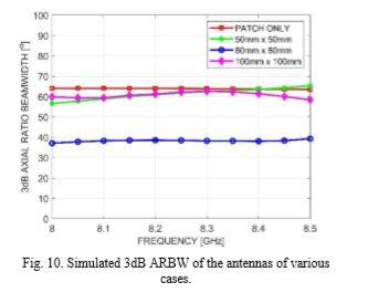
Product Spotlight
APV1111GVY
Panasonic

Panasonic PhotoMOS® Photovoltaic MOSFET High-Power Drivers
| SKU: | |
|---|---|
| Stock: | 3490 |
| Cost: | $3.95 |
