
Communication topology in the smart grid
Texas Instruments explain its G3/PRIME data concentrator options for use in smart grid applications. Today’s Automatic Meter Reading (AMR)/Advanced Metering Infrastructure (AMI) systems using power line communication (PLC) technology are network-based.
Multiple smart meters (in terms of PLC communication also known as service nodes) connect to a base node. This head of the network is located at the source of the sub-network, usually the MV/LV substation, while the smart meters are installed at the location where the energy is actually consumed - at your home, for instance. Each smart meter either connects directly to the base node or indirectly through a repeater (the repeater functionality is a mandatory feature for the service nodes). The collected data is then forwarded to the utilities’ head-end system using a different communication channel, e.g. Ethernet or GPRS.
It is now up to the utility whether the base node is part of a data concentrator or gateway. As the name implies, the data concentrator approach collects data from the smart meters and saves them locally. On top of that the security keys for the secure PLC connections between the base node and the smart meters are also stored in here. This fact may raise security concerns. The gateway approach provides better security and privacy since customer data is only stored in the head-end. The head-end system establishes a direct connection through the gateway to the smart meter. However, the smart meter must be reachable at the time of the communication request. Communication usually takes place during the night where a better quality of the grid in terms of noise and interferences can be expected, especially in urban areas. Tests in the field have shown good performance with the on-demand connection approach.
Hands-on hardware
Some work needs to be done in order to establish a reliable network with good connectivity. The common way to start exploring the PLC technology begins with simple point-to-point communication between two PLC nodes. The user gains knowledge about the PHY layer and does not need to bother about the MAC layer at this point. The PHY layer is the backbone of the network and enables a reliable network. It is recommended to at least touch the PHY at the beginning to understand typical challenges in a PLC network and the features of a PHY layer to address them. Terms such as modulation, code repetition and tone masking should be familiar after this exercise. Both the G3 and PRIME PHY layer can be extensively tested with the Texas Instruments Zero Configuration tools provided along with the TMDSPLCKITV4 PLC modem hardware, which includes two PLC modems.
The next logical step is to move up to the MAC layer. The PRIME MAC was developed from scratch and provides a managed network. Beacons and maintenance data are frequently transmitted. The G3 MAC is based on the IEEE 802.15.4 MAC which is unmanaged i.e. communication just happens on events (registration, data transfer, route requests, etc).
A good way to see what’s actually going on at the power line is to evaluate the PLC network with at least one sniffer located near the base node. This tool captures PLC packets, disassembles and displays them. This is very helpful during the learning phase to understand how the network works and later on, mandatory for debugging purposes. There are companies on the market providing turn-key sniffer solutions.
Software
To better understand the different hardware options for a data concentrator (or gateway) design described later in this article, a brief look to the software concept is necessary. The base node software is divided into two parts. The entire PHY layer and the lower part of the MAC layer is running on the TMS320F28PLC84 PLC modem processor, a member of the C2000 real time microcontroller family. The remaining part, the upper-MAC and layer on top (such as LLC (PRIME) or ADP (G3)) is running on a Cortex-A8 AM335x microprocessor of the Texas Instruments Sitara family. The MAC layer is split to optimise data traffic between the two processors communicating over a standard UART interface. The PLC base node software stack maintains the PLC network and provides functionality to the user application by two sockets. Custom applications can easily connect to the data and management port with a local connection and user defined port numbers. The certified G3 and PRIME base node software stacks are provided free of charge (the same applies for the certified corresponding service node stacks). Included in the distribution packages are example applications with source code for fast development of custom applications.
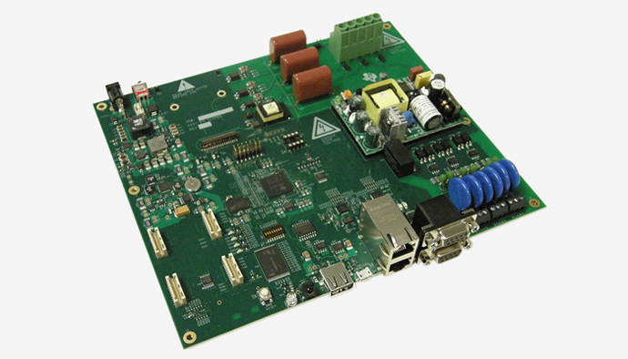
Above: Texas Instruments’ default hardware platform for the data concentrator/gateway end equipment is the TMDSDC3359 data concentrator reference design
Option #1
Texas Instruments’ default hardware platform for the data concentrator/gateway end equipment is the TMDSDC3359 data concentrator reference design. This board includes a rich set of connectivity. The connection down to the network, the PLC interface, is integrated on an exchangeable plug-in board to be able to address different global PLC frequency band requirements, e.g. Cenelec (Europe), FCC (US) or ARIB (Japan). The so-called System-on-Modules (SoM) hosts the modem processor and the analogue front end AFE031. The coupling hardware injections the PLC signal in all three phases simultaneously. For the connection towards the head-end the TMDSDC3359 provides a rich set of standard interfaces like Ethernet, USB, RS485 and RS232.
The main processor of the board, the Sitara AM3359, runs on Linux OS and leaves enough resources for customer application on top of the base node stack with up to 1,000 nodes and even more connections. To power the board two options are provided - the safe way is to work with the separate wall plug power supply because the OFDM-based PLC standards do not need the mains voltage or AC to operate. This comes in handy during the development phase of the product. When the reference design is tested in a field test the on-board power supply can be used instead. A base node is nothing without attached service nodes. Together with the already introduced TMDSPLCKITV4 reference design kit a simple two node network can be established in minutes.
The fact that the SoM board, which hosts the PLC modem, is being used in both the data concentrator reference design and in the TMDSPLCKITV4, enables another interesting hardware option for a base node, as described next.
Option #2
The Beagle Bone Black (BBB) board is a low cost development platform primarily used by the Linux open source community for a wide variety of applications. In TI’s design the BBB is used together with one PLC modem of the TMDSPLCKITV4 kit to form a simpler and more cost effective data concentrator compared to option #1. As we have learnt in the software section the base node software runs on two processors - the AM335x microprocessor and the TMS320F28PLC84 microcontroller. The AM335x is the main processor on the BBB and the TMS320F28PLC84 can be found on the SoM, which is part of the TMDSPLCKITV4, i.e. we have all components required. The only thing left to do is the physical connection between the two boards to get the base node hardware.
Luckily, the BBB owns a USB host peripheral and the TMDSPLCKITV4 a USB slave connection. The TIDesign TIDEP0023 provides in detail how to get from a standard software component downloadable from the Texas Instruments webpage to the running base node design. The documentation takes the G3 standard as an example, but a PRIME base node can be realised just the same way. Since just one PLC modem of the kit is used, the second PLC modem can be used as a node to actually get a one node network.
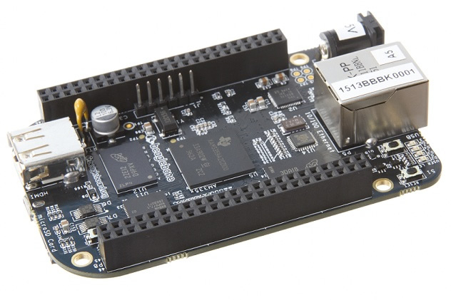
Above: the Beagle Bone Black (BBB) board is a low cost development platform primarily used by the Linux open source community for a wide variety of applications
Limitations compared to the full reference design are the one-phase coupling to the mains and the lack of communication interfaces, but this should not be a big issue for initial studies. For a real development option #1 is first choice. If one decides to move on with the BBB design and requires additional hardware, there might be an appropriate BeagleBone cape board available from a third party. These capes share a common mechanical and electrical interface plugging to the BBB seamlessly.
Conclusion
Texas Instruments provides different ways to get hands on a PLC network development. It scales from a complex design with full hardware feature set (Option #1) to a more cost optimised design using a slimmer hardware and the same software (option #2). Regardless which option will be used, the goal of fast prototyping can be accomplished.

Product Spotlight
APV1111GVY
Panasonic

Panasonic PhotoMOS® Photovoltaic MOSFET High-Power Drivers
| SKU: | |
|---|---|
| Stock: | 3490 |
| Cost: | $3.95 |
