
Making more of Doherty in LTE basestations
Steve Rogerson looks at how one company believes it is keeping 1930s Doherty amplifier technology up to date for modern LTE basestations.
Cellular basestations are facing an amplification problem as they roll out the new LTE networks, but it is a problem that one company believes it has gone a long way to solving. The problem lies within the multi-mode transceiver cards, most of which use a Doherty architecture in the amplifier. Despite this technology dating back to 1936, it does a lot to improve the efficiency and reduce costs.
Modern basestations with LTE use quite a complex modulation scheme as they try to squeeze in more data. This leads to a high amplitude variation. There can be a 6 or 7dB difference between the average signal power and the power spikes that can occur almost randomly. And these can be on any or all of the two to four channels in a basestation. When these random signals are added together and if the peaks line up in time, the difference can get up to 9dB.
The aim is to run a power amplifier as efficiently as possible, but if it is designed to leave enough headroom for these peaks, that means most of the time it is running at 9dB below its optimum performance, especially as, in a basestation, peaks normally happen less than 5% of the time. This is inefficient and where the 1936 Doherty amplifier comes in, splitting the signal up between a carrier amp that runs at the average power and a peaking amp for handling the spikes, as shown in Figure 1.
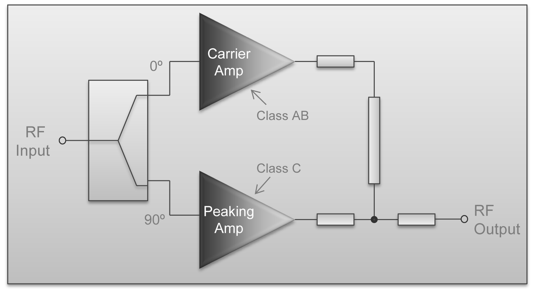
Figure 1 - A Doherty amplifier splits the signal between the carrier amp and a peaking amp for handling the spikes
“As is usual in RF,” said Mark Moffat, Managing Director of Peregrine Semiconductor in Europe, “everything has already been invented by much cleverer people in the past, but the technology wasn’t there then. The technology came later and verified what they said.” The carrier amp is optimised for the average signal. The peaking amp only turns on when it is needed; when the signal goes above the average. This means the carrier amp can be designed to run at optimum efficiency. It can also be a lower power amplifier with smaller transistors and less need for heat dissipation than would be needed if it handled the spikes. “This saves money for the basestation manufacturers because they don’t have to spend money on heat sinking and large power supply components,” said Moffat. “That is why Doherty is a good thing and why it is being evangelised by basestation makers.”
However, for this to work, the signal needs to be split into two, with the average signal going through one amp and the peak signal through the other. These signals then need to be brought together to produce the amplified version of the input signal, and this is where the problems begin. The alignment of the signals between the two amplifiers is critical. If they are misaligned they will not join up properly leading to distortion and a destruction of the efficiency that this architecture is designed to provide.
The problem is made worse because of the nature of the power transistors. These can have quite a wide variation in performance, which means the design has to be optimised for the expected average performance. But because the alignment is so critical, designing for the average can reduce efficiency by as much as 5%. To address this, passive components are normally used to adjust the phase based on the transistor performance.
If that wasn’t bad enough, about three-quarters of the designs use an asymmetric architecture – in other words the carrier and peaking amplifiers are not the same size. This makes sense because the power requirements of the two are different; if they were the same then the carrier amp would have to be much larger than needed and part of the point of using the Doherty architecture is to keep it to an optimum size so it runs more efficiently. However, with different sizes of amplifiers, the problem of bringing the signals back together again is even more complex. “This involves a lot of engineering effort and trial and error,” said Moffat. “There is no flexibility once it is implemented. And the efficiency gain is marginal because everything is done on average transistor performance.”
Solving the problem
One answer is to programme the phase and amplitude in final test so each path can be fine-tuned to increase the performance of each transistor. This is what Peregrine Semiconductor has managed to do with its Ultra CMOS MPAC (monolithic phase and amplitude controller), which digitally controls the phase and amplitude of each signal (see Figure 2). On the die is a signal splitter that, as its name suggests, splits the signal into two paths. The phase shifter and attenuator are both digitally programmed, separately and independently for each path. In final test, the device is hooked to the test system and an automatic routine calculates the phase and amplitude settings to achieve the best performance.
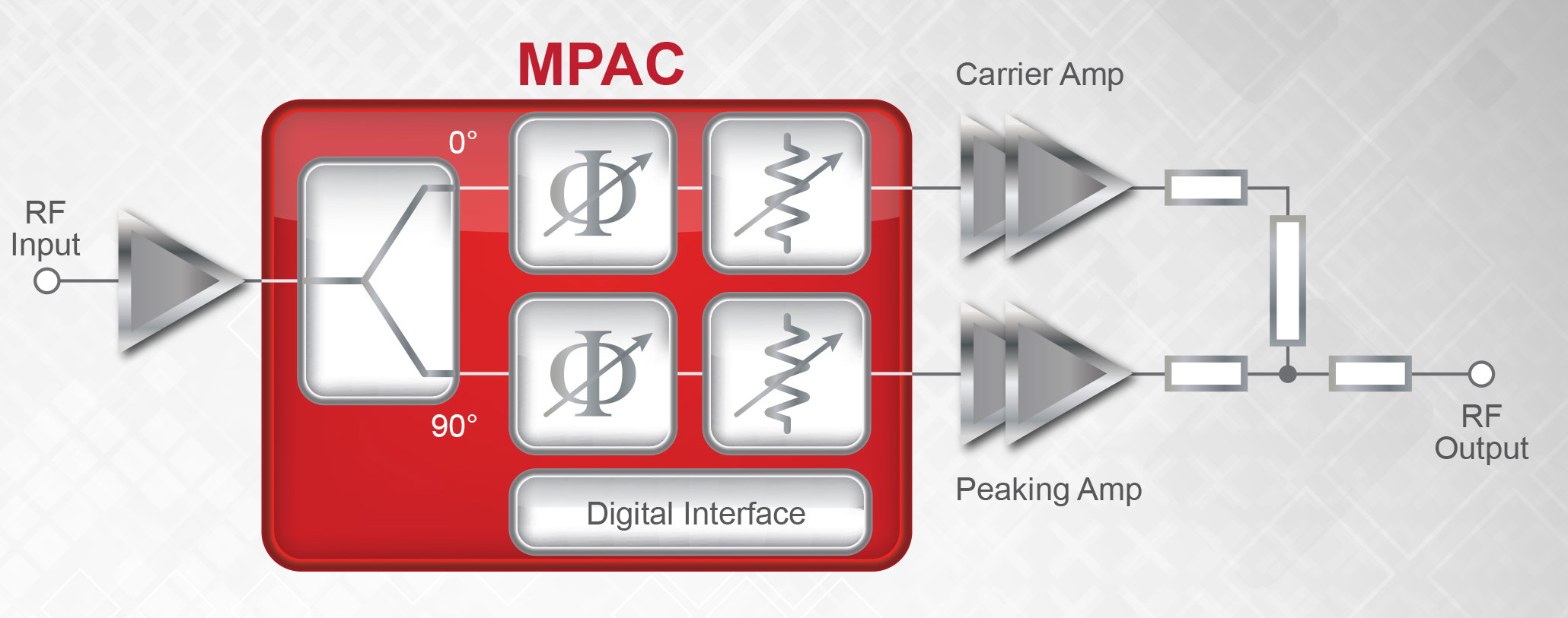
Figure 2 -The Ultra CMOS MPAC digitally controls the phase and amplitude of each signal
“It is set up specifically for the power transistors on the card,” said Moffat. “You get the best performance rather than an average performance from the transistors. We can integrate everything together on one die and it solves a very real problem for our customers.” He said this really made asymmetric architectures feasible with the advantages of using smaller transistors for the carrier amplifier. There are also reliability gains as transistors last longer when operating at the optimum performance level.
“You will now get the best power efficiency for your amplifier based on the transistors you have,” he said. “It also improves linearity across the frequency range.” The technology also supports digital pre-distortion, where a feedback loop will look at the output and the distortion characteristics and then pre-distort the input to improve these characteristics.
The snag with this approach is that it is one-time programmable. Once it has left final test, the characteristics programmed in are fixed for the card’s lifetime. But when installed, there may be environmental effects that could influence performance over time. These include antenna mismatching, component ageing, temperature variations, different modulation standards and so on. All of these could make the amplifier perform at below optimum. Peregrine is therefore looking at the possibility of modifying the devices in the field. This could be done using handheld test equipment, or in the worse case taking the card back to a service centre for an upgrade. “This is still hypothetical,” stressed Moffat.
So far there are three versions of the MPAC available and another in the pipeline. The PE46120 is for high-band cellular between 1.8 and 2.2GHz, the PE46130 is for 2.4 to 2.8GHz LTE and the PE46110 is for the old 0.7 to 1.0GHz low-band cellular. Not yet defined is the PE461xx for LTE-A bands. This will be out some time next year. Figure 3 shows the typical specifications.
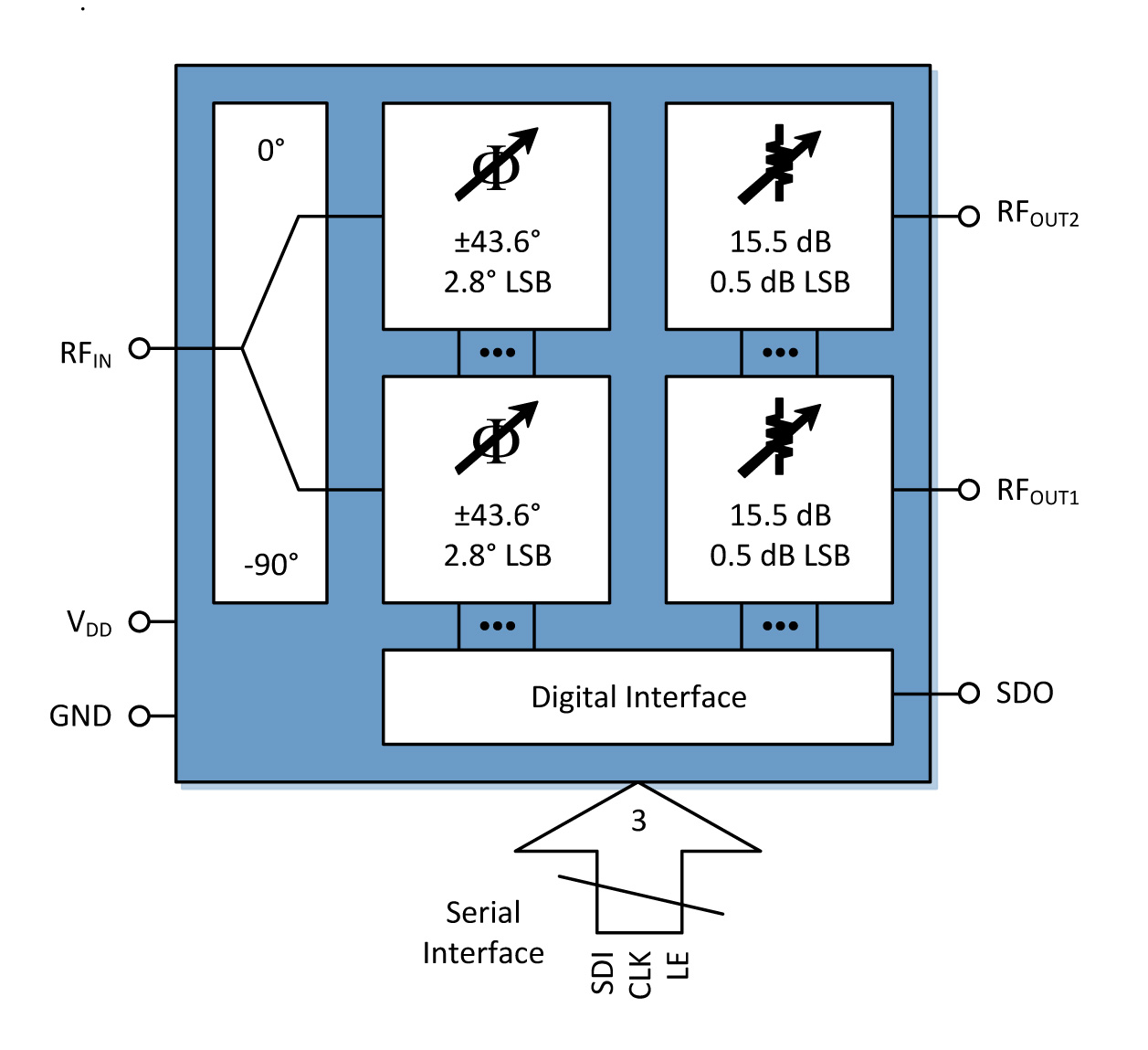
Figure 3 - Typical specifications for an MPAC
Though they can be used in single-mode basestation designs, where there will be one amp for GSM, one for CDMA and so on, the Doherty architecture really shines in more complex multi-mode architectures where the different signals are combined digitally and amplified. The market for these cards is dominated by Ericsson and Huawei; Ericsson has been involved in the development of this device. However, Moffatt sees other potential applications such as in smaller micro and pico cells as well as in wireless LANs and phase array antennas.
The main competition comes from Freecsale’s Adam Doherty controller. This uses three separate GaAs chips and one CMOS chip in a single package rather than having a mixed-signal product on one die, as Peregrine does. “This is a classic GaAs approach to these problems,” said Moffat. “They can’t integrate so have to do it as multiple chips. If there is an error on one chip, they have to throw the whole lot away unless you have more testing steps. It is more expensive whichever way you do it.”
The Doherty architecture is the preferred way of optimising efficiency in LTE basestations, despite its problems with aligning the separate signal paths based on the transistors used in each card. Now, a controller has been developed that can optimise these cards in final test so the phase and amplitude of the signals matches the performance of the transistors.
Product Spotlight
APV1111GVY
Panasonic

Panasonic PhotoMOS® Photovoltaic MOSFET High-Power Drivers
| SKU: | |
|---|---|
| Stock: | 3490 |
| Cost: | $3.95 |
